


1955-57 Chevy Air Ride Front Strong Arm Suspension
- Oct 11, 2013
By: Doc Frohmader of Air Ride Technologies
 One of the things I see as most admirable and effective about the 1955-57 Chevy is the suspension design. It was the first of the strong, lightweight, open driveline, modern IFS (Independent Front Suspension) cars that GM would do so well with for many years after. This IFS was very well designed and in many ways a better design than later GM IFS. I believe it to be superior by far to the 70's and 80's GM IFS, for example. For that reason, this suspension was more often upgraded as technology advanced rather than replaced. Racers and rodders both found that to make them shine on the roads and on the track only took a bit more tweaking instead of heavy modification (like sub-framing).
As part of a program to develop a series of bolt-on control arms called StrongArms, Air Ride has outdone themselves. Of course, they are in the business of fabricating and selling air suspension components, so these arms designed to be used with Air Ride suspension. In this case the kit is designed for use with their ShockWave combination air spring and adjustable billet race-style shock. If you’ve seen the AirBar rear suspension, you know that the StrongArm front kit is the perfect complement.
As you'll find with any Air Ride kit, it was carefully engineered to fit on real-life cars and to be installed with a minimum of modification to the original car. The control arms were tweaked to fit and function in the car as designed, but also to allow significant lowering without problems with alignment limitations. Made from heavy-wall steel tubing, these arms are much stronger than the originals and use modern bushings and ball-joints to keep service or replacement costs to a minimum.
Then there's the ride. There isn't a steel spring made that will allow you the control and adjustability of ride quality of a ShockWave. It's a matter of technology. Spring deflection rates for steel springs are linear. They are non-adjustable other than by replacement. A properly designed air spring has what's known as an S-shaped deflection rate curve where the rate rises as compression increases and drops as rebound increases (with a long central area where the rate remains fairly constant). Of course air springs are easily adjustable with air pressure.
The inspired combination of strong, stable StrongArm control arms and the ride quality of the ShockWaves make the perfect combination of strength and ride quality. With the adjustable shocks inside the ShockWaves, you can easily dial in the ride and performance qualities you like best – and change them as your tastes or conditions demand. Add a set of dropped spindles and disc brakes as a bolt-on and you've got a 50-year-old suspension fully capable of the kind of high performance handling and silky smooth ride that we only dreamed of in days past. So put away the cutting torch and toss that Camaro sub-frame back into the scrap where it belongs. Here's a much better way that doesn't require hacking junk parts onto your beautiful classic. This month we will cover the front installation while next month we will install the rear ShockWave and AirBar kits.
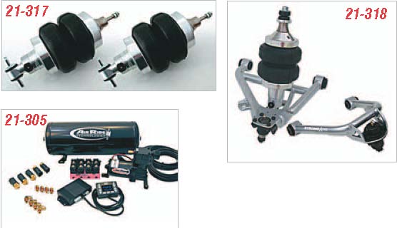
Parts Needed:
21-317 Front ShockWave Adjustable Shock Kit
21-318 Front StrongArm and ShockWave Kit
21-305 RidePro Air Compressor and Ride Control Kit
To order parts call 1-800-456-1957 or visit ClassicChevy.com
Tools Needed:
Coil Spring Compressor
Floor Jack
Ratchet and Assorted Sockets
Cut-Off Wheel
Grinder
Time Frame:
8 Hours
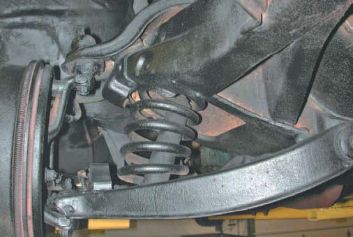
Photo #1:
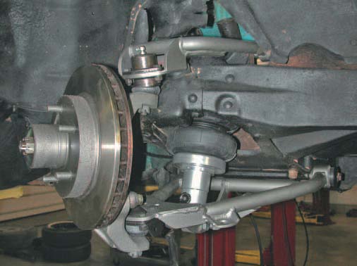
You might not tell the front suspension from a '55, a '65, or a '75 model GM car at first glance. There really wasn't a lot of change and most of it was negative on the newer cars. If you consider this, you might realize that hacking in a Camaro clip accomplishes very little but to make the car worth less.
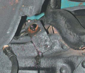
Photo #2:
This upgrade will involve replacing the original drum brakes with discs, so you might as well start off by disconnecting the flex lines at the frame connection.
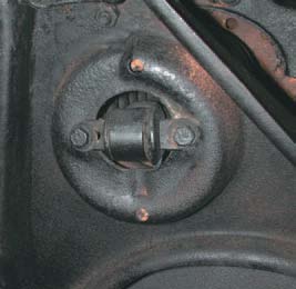
Photo #3:
Pull the two bolts out of the lower control arm to remove the shock. You can't get the spring out without removing the shock first. The top shock mount is approached from the top inside the engine compartment. This same location will be reused for the ShockWave mounts later.
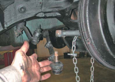
Photo #4:
Before you get too far, you'll want to break the tie rod ends and ball joints loose. A good way to do this is to loosen the nuts a little and then pop the joint on the side with a hammer. A pickle fork also works fine.
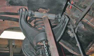
Photo #5:
We decided to work at removing the spring by dropping the lower control arm at the cross shaft end. You'll note the lower ball joint is under the arm so it would have to be lifted up while the inner end can just be dropped down. Be careful, work intelligently, and stay safe. It is best to install a coil spring compressor at this point to keep the spring from flying out and damaging you or the car!
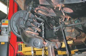
Photo #6:
Lower the jack down slowly to release the spring pressure and remove the spring.
Photo #7:
Now you can pop the lower control arm off the ball joint and get it out of the way. You can also pop the upper ball joint and remove the whole brake and spindle assembly and get it out of the way. Remove the upper control arm at the studs, keeping the shims together. While the car will have to go in later for alignment, these shims should go back into the same location. You can see here where the upper shock mounts are.
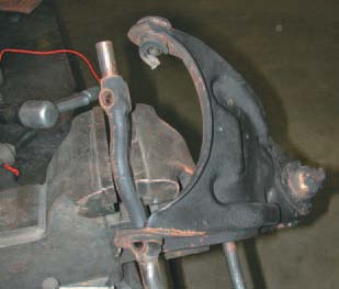
Photo #8:
Both upper and lower cross shafts must be removed and reused from the control arms if you are using P/N 21-318 kit that includes the new upper and lower control arms. If you are installing just the ShockWave shocks P/N 21-317 with your stock control arms, you may skip the next two steps. Start by driving one of the bushings out from the inside out. Then you can slide the cross shaft back out of the other bushing and into the hole in the control arm. Then back up and it will come out completely.
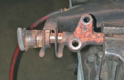
Photo #9:
The same goes for the lower cross shafts. Here you can see how the bushing is pushed out from the inside.
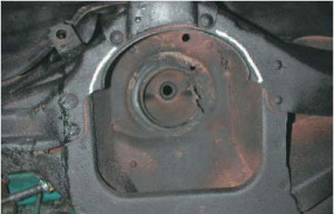
Photo #10:
The new ShockWave shocks P/N 21-317 (included in kit P/N 21-318) require a little more clearance than the steel coils. Marked here is the area that must be trimmed. Don't worry, it will not alter the strength of the frame at all and if you do a nice job of cleanup you probably won't even know it was done.
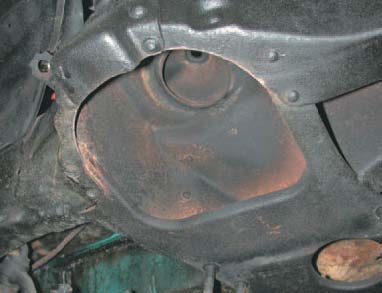
Photo #11:
See what I mean? All you have done is a little light trim and you'd have to crawl under the car and up into the pocket to see the modification.
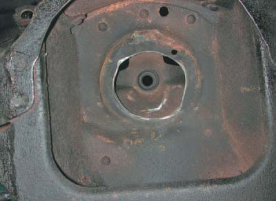
Photo #12:
Up inside the spring tower you'll see a lip that was made as part of the stamping process. You have to grind this flat and open up the hole just a tad for clearance at the top of the ShockWave shocks.
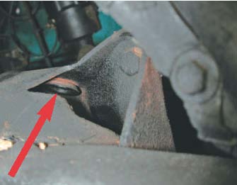
Photo #13:
If you look at the top of the tower where the original shock mounted, you'll see a bushing was crimped into the hole. It's wide at the bottom, so you'll grind the lip off the top side and drive the bushing down from the top.
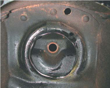
Photo #14:
Ready to go back together, clearances checked, we sprayed a little touch-up paint on the bare metal.
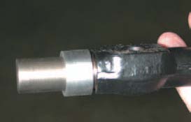
Photo #15:
The upper cross shaft gets a steel bushing pushed onto the shaft on either end. This adapts to the new, modern bushing used in the StrongArm kit and saves having to get vintage parts.
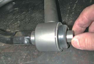
Photo #16:
The outer end gets another bushing – actually an extension – again so the new, larger bushing can be used on the original cross shaft.
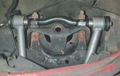
Photo #17:
Just bolt the new upper control arm in place using the original hardware and original shim packs. It couldn't be easier.
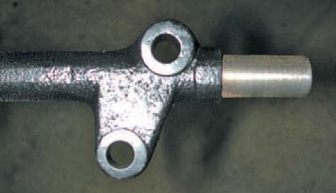
Photo #18:
The lower shaft also gets a little change so modern bushings can be used. Look at the boss on the shaft as it came off the car.
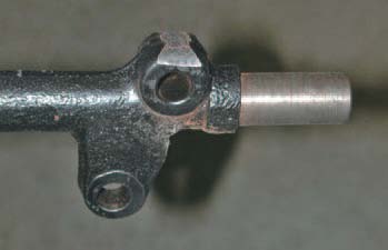
Photo #19:
On one end only, you have to shave a little off the short boss. This allows the shaft to slip into the control arm end when inserting the shaft before the bushings are installed.
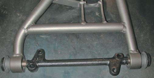
Photo #20:
The shaft has to be worked into the StrongArm before you try to push the bushings into the arms. Make sure you have the orientation of the shaft and arm right before you press the bushings or you get to start over.
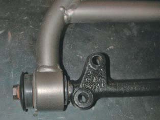
Photo #21:
Again, original hardware is reused with the original cross shafts. Believe me, this saves you a bunch of cash using original parts instead of designing and fabricating new shafts and related parts.
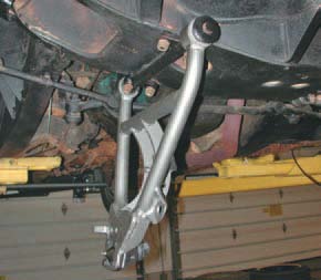
Photo #22:
Bolt the lower control arm onto the original location. Crank the mounting bolts tight but leave the bushings (upper and lower) loose until you have them at ride height. Bushings are in tension above or below ride height if installed right.
Photo #23:
The upper end of the ShockWave shock has a bayonet mount and you just slip it into the old shock mount hole. There is a urethane bushing on top and bottom, a large flat washer and two nuts to cinch the connection.
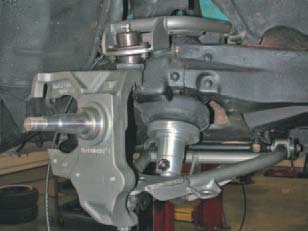
Photo #24:
On this car the owner opted for a two-inch dropped spindle.
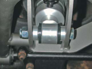
Photo #25:
The lower end of the ShockWave shock mount is the control arm itself. Note there is a spacer on either side of the ShockWave.
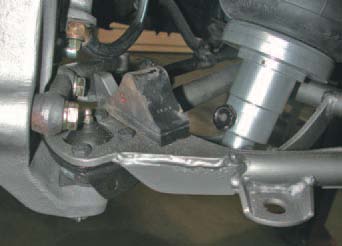
Photo #26:
The original lower control arm bumpers come off the old arms and bolt to the StongArms. No detail is ignored, and it all works like it was designed that way – and was!
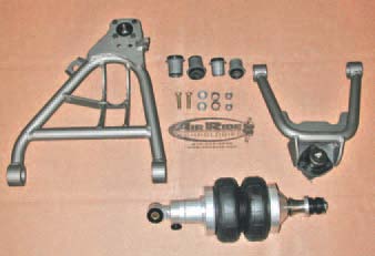
Photo #27:
The complete kit for the tri-5 Chevy StrongArm front suspension. Designed to be easy and uncomplicated as well as bring your project into the new century.
The ShockWave shocks are fully adjustable for ride height and quality. Both kits P/N 21-317 and P/N 21-318 are compatible with the RidePro compressor and ride control kit P/N 21-305.
Shop for Tri-5 Chevy parts at www.ClassicChevy.com
Follow us on our Tri-5 Facebook page. Click here and Like us!